COMPONENTS & INTERFACES
Select the system.
Then specify the parts.
Start with the engine and installation requirements. Confirm the components, interfaces and delivery scope together before choosing individual parts.
Discuss your engineAIR & FUEL
Throttle body integration.
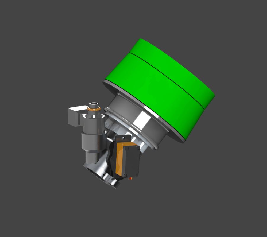
Fit is more than bore diameter.
Check mounting geometry, intake transitions, actuation, injector position and the available space around the engine.
- Engine-side mounting dimensions
- Intake and air-filter connections
- Throttle travel and servo clearance
- Fuel fittings and service access
CONTROL & DELIVERY
Make the interfaces explicit.
| Integration area | What to establish |
|---|---|
| ECU | Request the current technical documentation for supply voltage, connector pinout, inputs, outputs and supported communications. Do not assume that all ECUs share the same interfaces. |
| Injector and pump | Match fuel type, injector flow and operating pressure to the selected system. Review the pump and regulator together. |
| Sensors | Confirm which sensors are supplied, where they are installed and how their signals are connected. |
| Wiring harness | Define connector mating halves, cable lengths, routing, strain relief and installation clearances. |
| Included items | Ask for an itemised configuration so that supplied parts, customer-supplied parts and adaptation work are clearly separated. |
PREPARE THE INSTALLATION
Use the retrofit checklist.
A short interface review before assembly can expose mechanical and electrical mismatches early.
Read the integration guide